We bought a lighted Christmas tree from Amazon that had RGB lights. It lasted a season before dying. This year I decided to make a Christmas tree topper for my wife as Christmas is her favorite holiday. It involved designing a small circuit board for the LEDs, reflowing the LEDs in a toaster oven, designing and printing the topper, writing code for an ESP32 to drive the LEDs, and creating a small website to easily control the lighted topper.
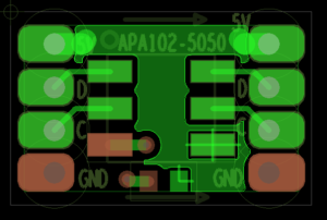
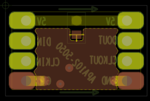
To start with, I wanted to use some new LEDs I hadn’t used before. The APA102 LEDs (also known as Dotstar) are a little more forgiving on timing than the standard Neopixel LED. I purchased the LEDs and a breakout board from Adafruit. Unfortunately I didn’t like the layout of the board as it had only one power and one ground connection which was not conducive to multiple LEDs as I’d have to share connections. I designed my own board with 4 connections on each side so I had power and ground in and power and ground out as well as data and clock in and out. The boards pins were on 2mm spacing so I could use headers as an easy way to wire in and out.
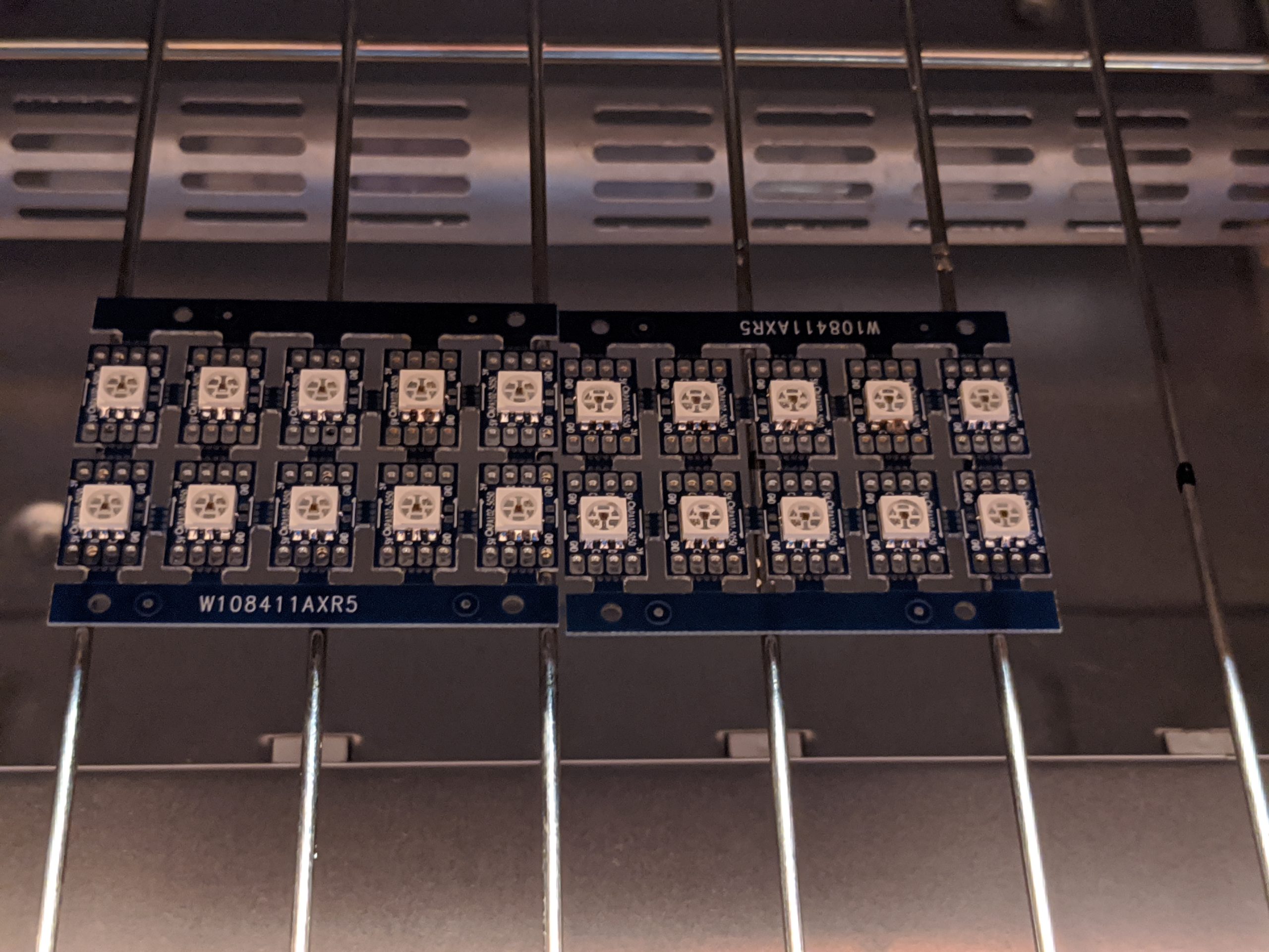
After I had the boards designed and ordered I had to solder a bunch of LEDs. I decided the best way would be to use my reflow oven I made for Ben’s show, seen here: https://www.youtube.com/watch?v=ckcHyMxqesM&t
I used a paste syringe to apply the solder, then ran it through the reflow oven. I had some failures to do with overheating the parts because my thermocouple setup inside the oven is not ideal. I will address that in the future so I don’t ruin anymore LEDs.

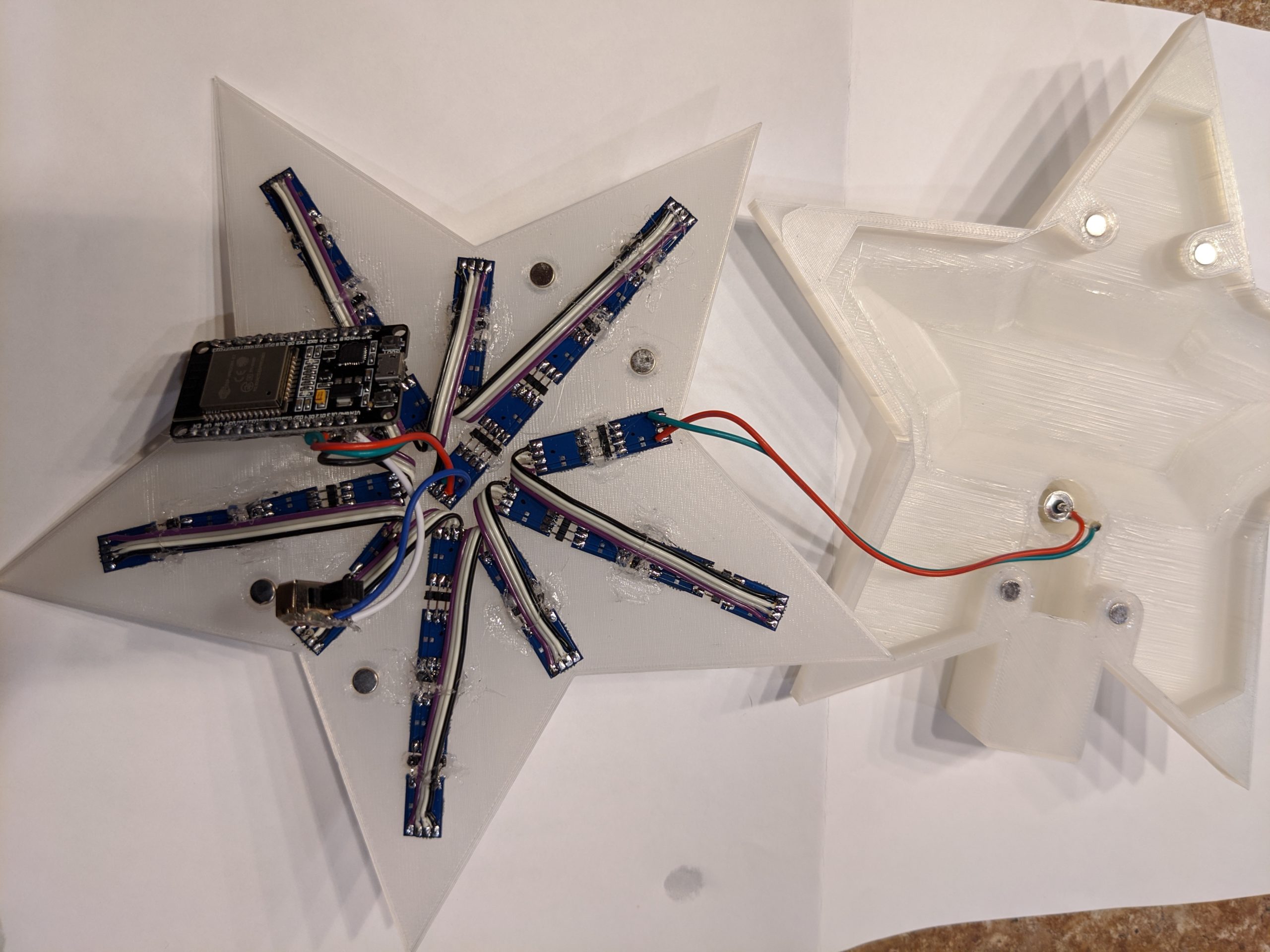
After I had the boards done I had to do the design. I designed everything in Fusion 360 and printed it out on my Prusa MK3 as large as I could get it. I made a two piece design with the front half housing the LEDs and being hollow and a few spots for magnets to attach to the back half. The back half had a sunken area to allow wiring and the controller board, a spot for the power connection (5V), magnets to attach to the front, and a hole/stand for the tree to go into.
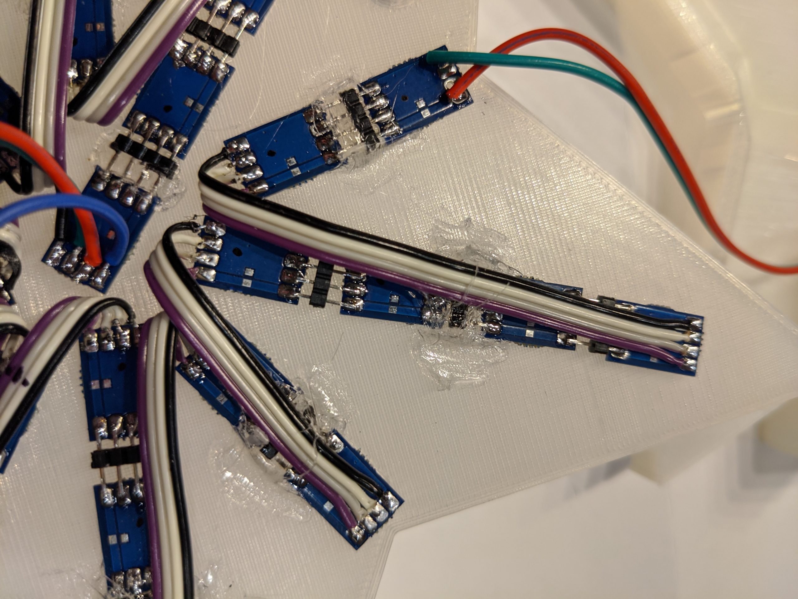
For wiring, a barrel jack is the connection for the 5V power from a wall wart. That goes into technically the last LED in the chain and it is daisy-chained through the other LEDs all the way to LED 0 which has four connections to the ESP32, 5V power, ground, MOSI, and SCK. The power is switched so it can be turned off during USB connection to prevent the wall wart from feeding my computer’s USB port with 5V. Each LED has 8 connections, the 4 on the left are Power, Data In, Clock In, Ground, and on the right Power, Data Out, Clock Out, and Ground. Power and ground are pass thru while the data and clocks pass through the LED which acts as a shift register. I used 2mm headers to connect each LED to each other where I could, and at the ends I used ribbon cable to return to the center. If you look at the LED at the center, that is LED 0, then count outwards and counter clockwise for the data path.
After everything was wired it was all about the code. First time using the ESP32, I followed some examples from random nerd tutorials https://randomnerdtutorials.com/esp32-web-server-arduino-ide/
and combined that with my code for my dice lamp I created a few years back https://blog.colecago.com/?p=743 . I added a new mode not used on the dice lamp and called it StarBurst and basically it lights the LEDs in a ring going faster as it goes outwards. I also changed the inputs for changing speed, brightness, and mode from buttons to webserver link hits. See the animations below.
Color track. 
Color to color smooth fade. 
Rainbow pinwheel. 
Random color fade in and out. 
Random color star burst. 
Star burst on tree.
After I had all the animation modes working I put up a website on my internal NAS with links to the tree topper to change all of the settings.
To make one yourself, the 3D files are located here:
https://www.thingiverse.com/thing:4112353
or here:
https://www.prusaprinters.org/prints/18177-lighted-christmas-tree-topper-dotstar
You can buy bare boards here:
https://www.pcbway.com/project/shareproject/APA102_SPI_LED_Breakout_Board.html
You can buy LED’s here:
https://www.sparkfun.com/products/16345
ESP32 was purchased from here:
Code is available here:
Thank you so much for posting the photos. Do you have e.g. Eagle files for the circuit boards? Please excuse me if this is a silly question. I have very little experience with home-brewing of printed circuit boards and it is mostly the magic of Merlin to me.
Yeah I can upload my gerbers. I just want to try my latest rev first as I messed with the ground connection when I ordered a new set with the missing rear silkscreen. I ordered them from pcbway, I’ll post them there and link it, you can order from the link and I get a cut or you can download the gerbers and choose your favorite board house. Eventually I want to sell populated panels on tindie but that will be a few weeks, I’m waiting to test some HD107S LEDs which are faster and available in bulk.
That is quite fine. Please take your time. This is a project I’m planning for the October time frame to be ready for Thanksgiving Day or thereabouts. I do want to mention that I have some very young neighbors — as in well under 10 years old — and I have a tradition of letting the children decorate the Christmas tree, all except the very top of it. My goal is to wow the kids (and of course all the adults) with your tree topper, while enhancing the safety aspect as much as possible. You never know where a little hand ends up. Or what a little kid sticks in his or her mouth, eeek! But I’ll watch the little ones with the greatest attention.
Okay tested my boards, they seem to work fine, I did fry a couple more LEDs but that’s my reflow oven, I really need to sit down and work on that thing. Be very careful when using these LEDs they are sensitive to heat during soldering. I chose the share button on my PCBWay account which is where I ordered the boards, but there is a link to download the gerber files if you choose someone else. It looks like they are running a design contest currently, so bonus!
I don’t have the panelized gerbers as they designed the panels themselves, I’ll see if they can get me them so I can upload my 3D base which I used for their solder stencil. This is the second time I’ve ordered these boards with slightly different gerber files and the panels came out the same, so its possible if you order a 2×5 panel of them they will also be the same size and I can share my stencil base with you if you want to solder using paste.
https://www.pcbway.com/project/shareproject/APA102_SPI_LED_Breakout_Board.html
Let me know if you have any problems, you can also email me directly, email is on the contact me page.
This looks great! Tough, I have some questions: What kind of barrel jack did you use for the power connection? And what type of filament for the 3d printed parts? And did you use any specific magnets to join those parts?
Thanks for the interest!
I used these barrel jacks:
https://www.amazon.com/dp/B07FK6MMGH/
I typically use some type of 5.2×2.1mm barrel jack on all my 5V projects. The magnets were 6x2mm neodymium magnets. And the filament is just clear PLA printed on an FDM printer.