This project is a bit outdated at this point, we are working on a simplified system people can use to integrate a wireless/ultrasonic following system into their projects, but its a bit far off, until then Elliot made a more up to date project using available components and has code available: https://elliotmade.com/2022/05/04/ultrasonic-direction-and-range-finding-hack/
Back in November I won a hat from Ben Heck, the host of the Ben Heck show produced by Newark Element14 http://www.newark.com/ and http://canada.newark.com/
I went and picked the hat up in person and talked to him and his assistant Alyson, they were finishing up the latest episode of the Ben Heck show. See here for more info
http://colecago.org/blog/?p=38
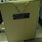
During the visit, it was brought up that I might be able to help on a future episode. Well that day came February 4th. The project was robot luggage. We started out by brainstorming over Skype. I had thought about this prior and this is what we decided on:
2 Ultrasonic sensors (receivers) on the luggage, 1 Ultrasonic sensor (transmitter) on the person (the target), 1 Wireless transmitter/receiver on each. The wireless is used to initiate the remote ultrasonic ping on the target. I thought this was the better route than using wireless RSSI on the transceivers for a few reasons;
– We don’t know what frequencies are in use in an airport and don’t want to be interfered with
– Wireless bounces a lot and is strange sometimes how it is affected by humidity, near ground effects, etc
– If not using RSSI and instead using Time of Flight, you’d need a very fast micro to record the distance, Ultrasonic sound travels much slower and its easier to discern a distance
I went to the shop the next day to do the recording. It was a little bit weird being on camera as you can tell I didn’t do the best acting in the beginning. It became easier and more comfortable later on. The recording day was all rehashing the design for the camera. We went over why we chose what parts, the mechanical design of the device, dimensional analysis for the speed and many other things. It was about 4 hours of work for 8 minutes of video.
Our next recording date was several weeks later as we needed to get the parts in. That day consisted of more of the mechanical work and testing out all the electrical components. Ben made a preliminary wheel, we soldered wires to all of our electronics and mounted them and added batteries. I had a lot of trouble working with the motor drives because everything needed to be sent in hex and it’s hard to find a good terminal program in windows7 that lets you do that, had I brought a windows xp computer, I could have used realterm, which is my go to terminal. I ended up using XCTU which is digi’s terminal program, originally meant to configure the xbee chips. It was not supported on win7 but it worked.
Also, a note on UART dyslexia, if you are designing anything with a UART interface, please, please, mark your terminals in some manner like TXOut, RXIn so we know what direction the traffic should be. Most things are marked TX and RX but they don’t indicate if its the TX of that device or the one connecting to it, I’ve seen it both ways on modules that use UART. Here is the best quote I’ve seen on this
Before purchasing this part you need to know if you have a condition called UART dyslexia. This is a neurological disorder that will render you incapable of properly wireing this device no matter how my times you triple check the the wiring. I have this disorder and I have only found three possible solutions:
1) Find someone else without UART dyslexia to wire it up for you
2) When you get the board, immediatly scratch out the silk screen for the TX and RX pins. You will have a better chance attaching the wires at random than attemping to determine the proper connections in your screwed up head. Test the device and if it doesn’t work swap the lines. The advantage of this approach is that you didn’t spend hours trying to figure out the wrong way to wire the connections.
3) Try to figure out the proper connections and do the opposite of what you think is correct. I have had some success with this approach. -MotiveForce sparkfun comment
I got some wheels spinning and we got the wireless generically working, and that was about it for the day. One big comment about the transistor inverter-
Originally I wanted to do a NPN inverter but I wanted the signal pulled low so it was always low if the input was floating, this required me to change to the pnp approach, I switched the arrow, but did not switch the pins of the device. Emitter should have went to VCC and collector to the signal out/pulldown resistor. That is why it did not work. The arrow represents the internal diode (because of PN junctions) of the device and you can think of it as the direction the current will flow, so of course current cannot flow backwards through it and the device didn’t work. That was a fundamental mistake on my part, not much to blame it on but nerves and working on the fly on camera.
(Supposedly the ping has an internal pulldown, if that is the case you should be able to remove the pulldown off the pnp transistor)
I was supposed to come up the next Saturday and Sunday, but I got pretty sick, so I sat alone in my lab all day Saturday working on code

Let me say this, I hate programming for Arduino. It’s a great platform for hobbyists and gets people into electronics and programming. There are a ton of boards out there and quite the following. Most Arduinos are based on AVRs which I use all the time at work. I figured I’d do it as an Arduino this time, and I did not enjoy it. This is how I expected the program to work
Decide to take a reading, send out a serial wireless command to do a ping, count on a uS timer until both left and right ping received, the distance is the turn value
I couldn’t find uS timers, so I tried the next approach
Decide to take a reading, send out a serial wireless command to do a ping, do pulsein to record time for one receiver, repeat for second receiver
This didn’t work as the serial library is so bloated that variable lag was causing my values to be off 50-150uS whereas the difference values I was looking for many times were less than that. I hooked up a scope and the end point of the value was bouncing but not the difference, it must be from inconsistent serial lag to the remote sensor. Basically I had to read them both on the same wireless ping to get accurate results.
Use interrupts, I set both ping sensors on an interrupt so when they changed state, I’d check the second sensor to see if it triggered, detatch the interrupt so it doesn’t happen again before I’m ready and then when I receive the next interrupt that is my distance.
Well, that didn’t work either, I think either the arduino doesn’t like detaching an interrupt within that interrupt or just how long it takes to do a digital read (which I didn’t know yet) was causing grief.
Next try, sit in a loop that’s doing uS delays and counting up (with a timeout) and polling the pins to see when they change (because they received the ping back), then receive that, set some flags so you know which one went first and wait for the second one, then do the difference value etc.
This didn’t work either, I think because digital read takes a very long time (longer than it should). Once I changed it to read directly from the port (PINB & 0xyadayada) that approach worked.
The whole project I was struggling with arduino based problems, if I had better access to the lower level parts of the AVR, especially timing interrupts, I would have been fine. Once I got the error values working correctly, the project worked great. Next time I skip the arduino and go avr studio and straight c. Once I got the terminal result below, I went to bed
Error: -26
Direction: Left
Error Sum: -262
Error Correction -9.12Error: -17
Direction: Left
Error Sum: -490
Error Correction -9.15Error: -13
Direction: Left
Error Sum: -503
Error Correction -8.28Error: -10
Direction: Left
Error Sum: -513
Error Correction -7.63Error: -2
Direction: Left
Error Sum: -558
Error Correction -6.08Error: 1
Direction: Right
Error Sum: 1
Error Correction 0.26Error: 5
Direction: Right
Error Sum: 10
Error Correction 1.35Error: 9
Direction: Right
Error Sum: 19
Error Correction 2.44Error: 18
Direction: Right
Error Sum: 90
Error Correction 5.40Error: 23
Direction: Right
Error Sum: 113
Error Correction 6.88Error: 28
Direction: Right
Error Sum: 141
Error Correction 8.41
I was moving the target from left to right in front of the receivers, Error was the difference between the left and right times, Direction was which direction to turn, Error sum is basically the integral term before weighting, correction was what to add to the turn value.
The next day I showed up with my own box of kleenex, hand sanitizer, and trash bag as to not infect Ben and we went to work. We got everything installed, Ben finished the 3rd leg and handle and I changed the code so it would send the turn value to the motor controllers. Off the bat, it worked pretty well, had to do tweaking but I was surprised at how well it worked increasing and decreasing the separate wheel speeds based on location of the target. I added a distance timeout for too close and too far, tweaked the P and I weights, and added flashing lights for status. We tried a smaller battery pack but it died pretty short into it so we went back to the huge lead-acid batteries. We got it following well and then I left. Ben and Alyson finished closing up the front, added some decoration, and finished the taping. All and all, it was an awesome experience, I had followed Ben’s work on HaD and it was a once in a lifetime experience to work with him, I hope I get to work with him more in the future.
Watch the full video below
Here is a little bit longer explanation of the program flow
Functions:
Setup()
Loop()
doPingDiff()
setToZero()
updateDrives()Powerup
Setup-
Set up the 3 serial ports
Serial is for debug at 9600
Serial1 is for motor control at 38400 and 2 stop bits!
Serial2 is for zigbee for remote ping
Set up leds
Send some commands to motor controlMain
Loop-
Clear out important variables like difference and distance
See if handle switch is in disabled position
Flash status LED
If Not Disabled; Do 4 pings and average difference result and distance result
If too close to person (based on distance); disable
If Difference looks good and not disabled; update the drives and
clear timeout; else increase timeout
If timeout counter is too high, disable
If disabled; set the drives to zero and blink lightsdoPingDiff-
Do the high low thing to start both receivers
Send Zigbee start command
Wait for either left or right sensor to go to zero or timeout; record
that setpoint
Wait for second sensor to go to zero or timeout; record that setpoint
and break loop
Calculate the difference by subtracting
Calculate the distance by adding both values and dividing by 10 (for
scaling speed)
Return the difference (which is our error)updateDrives-
Calculate the direction of the error (basically left or right turn)
If direction has changed, clear out the error sum (integral part of PI Loop)
Add Error to the Error Sum
Calculate turn value by doing Kp*error + Ki*errorSum where Kp and Ki
are set to 0.5 and 0.25 respectively and then add to 128 which is our
Zero
Calculate the speed by taking our above distance divided by two, then
subtract from 128 because forward is 0-128 (with 0 being max allowed)
Make sure turn isn’t greater than 250 or less than 5 (preventing
overflow or underflow)
Make sure speed isn’t less than 5 (preventing an underflow)
If Debug is set output all of these numbers through the Serial port as wellsetToZero-
Set speed and turn to 128 (bidirectional data around 128, 0 is max
one way 255 is max other way
I’ve also attached the code for download. I’ts a .c file, but is actually the .ino, wordpress doesn’t like .ino files so just rename it to something.ino

I don’t have the dimensions of the luggage, but here is a build list of the electronics:
Motors and controller- http://www.robotshop.com/drive-system-12-volt.html
Microprocessor board (brains)- http://www.sparkfun.com/products/10744
Ultrasonic Sensors (x3)- http://www.parallax.com/tabid/768/ProductID/92/Default.aspx
Wireless Boards (x2) – http://www.sparkfun.com/products/10414
Power Convertor – Don’t remember, it was some off the shelf Buck Switch Mode powersupply with 5V output


