Well, this will be a quick little post, mostly for a location to drop some files. I made another Ben Heck Show appearance, this brings me up to 3. The video can be seen here
It was a cool experience as it always is. Some guys from Engadget were there to film as well and it was cool to talk with them. Also Ben and I got in an abbreviation contest which was fun. VHDL stands for VHSIC Hardware Description Language, with VHSIC standing for Very High Speed Integrated Circuit. That is the coolest one I know.
Anyways, a few people have asked for the code and such so I will embed it at the bottom. I have the Android code and the TI Launchpad firmware code, both in separate zips. The Android code was written for either Jellybean or ICS, don’t remember which, and that was for the rotate command, like the pot stir app. The APK is in the zip file. I didn’t take the time to really document as I’ve been a busy guy. Hopefully I’ll get to do a life update and an update on my ShapeOko CNC machine shortly.
I figured I would write a better Buildhealth wrapup than just the videos I posted.
First of all, I have a playlist for the Buildhealth videos, see them here
Planning:
I heard about the Buildathon from Sector67’s Google Group. I talked to some friends about forming a team. A few weeks prior I was thinking about not going, then Meg re-insisted I should go after the April 3rd Sector67 meeting where Mark brought up the Buildathon. I talked to my team, they were still on and we signed up for some Google + chats to discuss ideas. I knew from the beginning I wanted to do hardware, but not sure what yet. We had a Google + hangout later that week to discuss. I had an idea about making a rumble belt for deaf people that took in several audio inputs on a necklace or collar type of device and rumbled with the intensity, frequency, and direction of the sound. I still think this is a great idea, but it doesn’t really fit healthcare. I forgot all about the Google + hangout on Monday to discuss and apparently everyone else did too. I recapped with them later in the week and because of conflicts, all of my teammates dropped out (had 2 guaranteed, 1 never heard from, and 1 possible). I was considering not going, and then I decided I should go even if I couldn’t build hardware just to support another team. On Thursday night I had this great idea of a UV System to kill germs. I told my team I was still going and started making preparations and getting supplies. I borrowed a Roomba and some random parts from Sector67. Then I got some messages from Steve saying he was back in. We planned on and off the rest of the day for our ideas and packed that night to leave.
Arrival:
We arrived at 9am and parked the car. Tim introduced himself to us and then showed us the upstairs where we could put our stuff. Steve and I moved a table into our empty room and then unloaded my car into the room. I had a lot of hardware supplies and tools. After unpacking we ate some breakfast and sat at a table with fellow buildathoners and talked a little bit while we waited for it to start. A little over 40 people showed up, but not all were participants in the challenge.
Introductions:
The buildathon started with some basic introductions of the organizers as well as talking about the space and goals for this event. We broke into small groups and did introductions. Then Tim Bartholow talked about some staggering health care numbers. After the data was gone over, the submitted problems were explained. Some of the people that submitted problems were actually present, so they explained them. As Steve and I had an idea beforehand for a solution, I gave a short description of the problem and solution we wanted to work on. Then everyone broke into groups to discuss the submitted problems. No one joined us at this point and Tim released us to go work on our problem/solution.
Designs and Lunch:
We sat in our rather warm glass room and worked on some designs. I would take care of the Roomba and all involved with that and Steve would do the ceiling unit and the rotating reflector unit. We ate some lunch, then continued designing. A journalist from the Journal Sentinel stopped by and interviewed Steve and I about the buildathon and our idea. After she left, we finished up our shopping list and left to Menards. It was about 2pm at this point.
Menards Trip:
We spent a long time at Menards. First we got the lights, Steve picked out Daylight CFLs as they are bright and produce whiter light than incandescents. We picked up some wire, and then some low voltage halogens for the Roomba. Next we needed hardware for the rotator. Steve found some lazy suzan hardware near the castors and we found some vacuum belts with help from the associates. We also got some wooden dowels, nuts and bolts, and some sliding door handles which were originally going to be used just to trace a circle on our cardboard for the rotator. We picked up some reflective cardboard for the rotator, and got some much needed duct tape and industrial velcro. We made it out of there $80 poorer.
New Member and Dinner:
When we came back, Alex was waiting for us. He wanted to join our team so we explained what we wanted to do. We tasked him with building the ceiling fixture. I hooked the Roomba up to my power supply and turned it on to know what to expect. You have to hit the power button, then hit the clean button. I started taking it a part to hack into it. Around dinner time we had two more people join us, Emily and Jesse, Emily researched current UV technologies and killing pathogens and Jesse helped build the cardboard topper for the lights on the Roomba. I ate some dinner with Chris from Sector67 who stopped by and Tim Bartholow. Then back to work on the Roomba.
Roomba Power:
Alex finished the ceiling unit and Steve was making good progress on the rotating unit. He had a good base but was having trouble getting the belt to connect to the motor properly. We decided to use the two sliding door handles/cups back to back as the pulley for the belt to ride on. Our belts were too small and Menards didn’t have rubber bands (according to associates), so we duct taped them together. I soldered wires on all the Halogen lights, which was pretty difficult as that metal didn’t like to solder, and then gave them to Jesse to put in his topper. I then went to work on the power distribution of the Roomba. I hooked up some wires to the Roomba’s main power, hooked some wires to a perf board and then to the two 7.4V batteries in series and a switch. I powered up the Roomba and it worked fine.
Roomba Logic:
I needed a microcontroller on the Roomba to turn on all the relays, one for each light as they all draw close to an amp each, so four total, and also to act as a person pushing the buttons. I traced out the buttons I needed, added some wires, I planned on sending a 0V signal to initiate the power on and clean sequence as the buttons were connected to ground. For the lights, I tied the high side to the positive rail of the battery and the low side to the relay and the other side of the relay to ground. The relays switch ground to the lights, completing their current path. All 4 relays were switched on using using a single bjt as my micro couldn’t handle the current. I had a lot of trouble getting this working. I had a stable 5V and when I’d switch a relay, my power would die. Mark from Sector came by and asked me how I was doing. I explained my problem, how I switched out the regulator, bypassed the regulator, and I couldn’t figure out why it was failing. He asked about my caps on my regulators. I told him I didn’t have caps on them because I was running off of battery voltage and didn’t care about any ripple, I mean batteries make pretty clean power. I tossed a cap on the regulator and problem solved. Apparently regulators need a minimum capacitance or they go wacky, and not always apparently, because they could handle my micro alone. Well this fixed all my problems, but in the end, I wasted so much time with testing and resoldering connections, I knew I couldn’t implement a wireless link. I instead introduced a 10 second delay or so from switch on, to turning on the lights and Roomba function. I then moved on to the spinning light control.
Rotating Light Logic:
I already had the code down for the delay and relay turn on, I tossed this code on another micro. I found a 19V AC/DC convertor and hooked up another 5V regulator, this time with a cap, to power my micro. I used a BJT to both turn on the AC powered light and another bjt to power the motor. The motor spun really well at 5V so that’s what I used. I then hooked the power supply up to a switch and tied the relay to the lights. When I turned the switch, I waited 10 seconds and both the light and motor would start. This part was done. Steve did a great job getting this one working.
Ceiling Light:
This last light was the easiest. I cut open another power supply as I planned on using another relay. This relay was controlled by an inductive prox, our door sensor. So I would turn the switch on, and then when the sensor sensed metal, it knew the door was shut and would turn the light on. This worked pretty well. Once all three systems were done, we went to bed. I put our overnight videos on youtube and ended up going to bed at 4:30.
Morning Prep:
I woke up at 7:30 to begin our preparations. I cleaned all of my equipment out of our little room and swept the floor and table. I woke the guys up around 8 so we could install our system and work on our presentation. We mounted the ceiling unit using yarn, put the Roomba on the floor, and put our secondary surface cleaner on the table. We did a dry run of our system for our video here:
Alex and Steve had done most of the presentation the night before and this morning. So we finished up the build slides and tried to come up with the intro. Alex and Steve were to present most of the presentation and I just covered some of the build information.
Presentations:
We were the third group to present. As we spent 90% of our time working on hardware, I felt like our research was lacking a bit, we didn’t know our market perfectly, but it went over well. At the end, we took everyone over to our room and showed a demonstration. All in all it went well. All the groups finished their presentations, and all were good. I especially liked Triage.me presentation, even though the presentation part was filled with technical difficulties, the actual content and idea was solid. I really liked the website they put up and the text messaging service. A big thanks to DC414 for helping out Triage.me and their presentation by remote desktopping into the mac and displaying to the projector through their laptop. DC414 definitely were the hackers of the buildathon.
Results:
The judges consulted for a bit while a storm raged for a little bit outside. We lost power for a little bit, so I grabbed the Roomba in case we needed a little roaming light. They came back and presented the winning teams. See the video here:
Reality Check won third place, Triage.me won second place, and we won first place and people’s choice. This also included an invite to DC for the Health Datapalooza. We took a picture with Ken from HHS, talked to the other groups and started packing our things to leave.
Conclusions:
Buildhealth was great. I wasn’t expecting to do so well, and I’m glad I could do hardware. Tim put on a great event and I can’t wait for the next one. I met a lot of great people, from organizers and judges, to participants. I don’t feel our idea was as hardhitting as the other guys, and I hope they were not discouraged to flesh out their ideas into full products. DC is up in the air right now, waiting on word from HHS, this might not be the event for hardware guys such as us 😀 We’ll see, it would be a great opportunity. I don’t currently see the light at the end of the tunnel for us starting our own business around this idea, but you never know. This was my first Hackathon, but it won’t be my last.
Update: I’ve added the Teensy code below. Pretty simple because its just a delay. Wish I had gotten time to work on the wireless. I do a lot of serial work so rolling a protocol wouldn’t have been super difficult.
Not only did I put the electrical system together (and some of the mechanical), I also made the controller board and wrote all of the code.
AGV Controller Rev 1:
The first wireless controller was pretty rough. It was a two board design and had sliders to control the front and back actuators. It used gaming joysticks for the control, kind of video game style with one joystick for left/right and one for forward/backward. The sliders have tops on them, I just don’t remember where. I designed the placement in Autocad, then drilled and dremeled the case.
AGV Controller Rev 1 picture
AGV Controller Rev2:
Rev two took parts and ideas from a controller I built for a customer and built this beauty. It was a lot more rugged, had a larger battery, state of charge led’s, and an onboard battery charging unit. It used the large rugged joysticks. One stick was for forward/backward/left/right and the other was to control a conveyor on the top which we had to remove and send to a salesman later. It uses Zigbee (like the last one) to control the AGV. I did design this one as well, but I had a third part do the milling as I had some square holes as well as holes larger than our available holes saw.
AGV Controller Rev 2 picture
The AGV is also bluetooth controlled via an Android App I wrote after going to the Marakana Android school
We to make some motor mount encoders. The idea is to mount directly to the shaft of the backend of the motor and you would ziptie the cord of the encoder to keep it in place. We offered single and quadrature options. We designed a style in solid works, then had a representation of the encoder CNC’d out of metal to assist me in making molds.
Mold Rev 1:
I built mold rev1 from silicone, it was my first time doing something like this. Mold rev 1 was very thick and used screws for keying. I also used some screws or wires for the air and pour holes. It did its job, but not very well. The pour and air holes were too small and not connected very well because they were put in after. Still it got the proof of concept to work, I poured a few sets of encoders, all using polyurethane for their base.
Mold Rev 1 picture
Mold Rev 2:
To fix pour issues from Mold Rev 1, we remade the model to include air and pour lines. This helped me make Mold Rev 2. I used hexagonal spacers for keying. This mold worked very well and I did probably 5-6 pours to get more prototypes ready. The black encoder pictured below was actually poured from this mold. The quality is pretty good. It was one of several polyurethanes I was trying and was my favorite as it still had a slightly soft feel when done and didn’t have too many bubble issues. The Green encoder is one professionally made once we submitted our drawings to an injection molder. We are still in process working out quality issues with them. The last hole shows the circuit board that goes into the mold.
Mold Rev 2 picture with finished and unfinished encoders
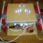
SwitchBox
I never have enough reliable switches and potentiometers around. I often have to hunt for working ones and then attach new wires to fit what purpose I was using them for. After being fed up for the last time, I decided to make a multipurpose switchbox.
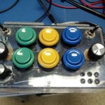
I designed the box below in Autocad then drilled everything out on a drill press. It features two 2-way toggle switches (upper left and right corners), one three way rotary switch (bottom left), six NO and NC Arcade pushbuttons (center), two 5k potentiometers (left and right sides), and six constant current LED’s which can be given 2.7-30 some VDC. I use LM317’s in constant current configuration for this. Below is the face for the Switch Box.
SwitchBox face picture
The top of the SwitchBox contains all my connections, all wago terminal blocks that you use a screwdriver in the top slot to put in your wire in the bottom hole. These terminal blocks will last a lot longer and hold a lot better than screw terminal blocks. Everything is labeled with marker, which is hard to see, and I made a whole lot of tinned jumper wires to connect to this to save myself time. This box really came in handy when I was designing the logic board for a door opener, which has a ton of inputs to it. But the main goal was to end frustration finding/repairing/putting wires on and getting shocked by my components.